the Creative Commons Attribution 4.0 License.
the Creative Commons Attribution 4.0 License.
 | 28 Oct 2020
Preparation of thin-film composite membranes supported with electrospun nanofibers for desalination by forward osmosis
Mohammed Kadhom
Khairi Kalash
Basma Waisi
Noor Albayati
The forward osmosis (FO) process has been considered to be a viable option for water desalination in comparison to the traditional processes like reverse osmosis, regarding energy consumption and economical operation. In this work, a polyacrylonitrile (PAN) nanofiber support layer was prepared using the electrospinning process as a modern method. Then, an interfacial polymerization reaction between m-phenylenediamine (MPD) and trimesoyl chloride (TMC) was carried out to generate a polyamide selective thin-film composite (TFC) membrane on the support layer. The TFC membrane was tested in FO mode (feed solution facing the active layer) using the standard methodology and compared to a commercially available cellulose triacetate membrane (CTA). The synthesized membrane showed a high performance in terms of water flux (16 Lm −2 h−1) but traded the salt rejection (4 gm−2 h−1) compared with the commercial CTA membrane (water flux = 13 Lm−2 h−1 and salt rejection = 3 gm−2 h−1) at no applied pressure and room temperature. Scanning electron microscopy (SEM), contact angle, mechanical properties, porosity, and performance characterizations were conducted to examine the membrane.


Forward osmosis (FO) is an osmotically driven membrane process that uses the difference in osmotic pressure between the feed solution and a highly concentrated solution (called the draw solution) to drive the pure water from a feed solution through the membrane to the draw solution. The FO process has many advantages over other types of filtration processes, such as its low or no trans-pressure, very high rejection for various contaminants, low membrane fouling tendency, and easy building and operating system. The used system is very simple and membrane support is less of a problem (Al-Furaiji et al., 2018; Cath et al., 2006).
One of the crucial aspects of developing the FO process is making a suitable membrane for this process. The ideal membrane has to be highly porous and thin, have good mechanical properties, and provide high rejection of salts and impurities (Ang et al., 2019). Thin-film composite (TFC) membranes have been widely used in reverse osmosis studies and proven to have excellent performance in desalination (Kadhom et al., 2016; Kadhom and Deng, 2019). Recently, TFC membranes have attracted more attention in FO applications.
Commonly, the TFC membranes consist of two layers: a thin selective film that permits water molecules to pass through but prevents salts and other contaminations and a support layer that provides the required mechanical backing (Ren and McCutcheon, 2014). The selective thin layer is typically prepared by the interfacial polymerization reaction of m-phenylenediamine aqueous solution and 1,3,5-benzenetricarbonyl trichloride, which is familiarly called trimesoyl chloride, organic solution on the support layer. The support sheet is conventionally prepared by the phase inversion casting method. Here, we adopted an emerging technology, electrospinning, to prepare the support layer. Electrospinning has some advantages over the traditional phase inversion technique, which include producing highly porous layers and generating sub-micron fibers with highly controllable properties (Waisi et al., 2019). These properties have led to introduction of these nanofiber sheets as promising alternatives for the conventional FO membrane's support layers. Bui and McCutcheon (2013) investigated blending of two kinds of polymer (i.e., PAN – polyacrylonitrile – and cellulose acetate) to make hydrophilic nanofibers for FO applications (Bui and McCutcheon, 2013). Huang and McCutcheon used nylon 6,6 electrospun nanofibers as support for TFC FO membranes (Huang and McCutcheon, 2014), while Chowdhury et al. prepared and tested a TFC membrane supported with commercial polyethersulfone (PES) nanofiber membranes (Chowdhury et al., 2017). All these electrospun nanofiber-based TFC membranes showed excellent performance over the commercial FO membranes.
In this work, a thin-film composite polyamide membrane was synthesized by reacting MPD and TMC on the electrospun PAN nanofibers' support layer and utilized in the forward osmosis process. The electrospun PAN nanofibers were prepared using a home-made electrospinning setup that was fabricated from locally available parts; highly porous and highly efficient nanofibers were produced using a very low-cost method. The membranes prepared in this study were mainly characterized by SEM and contact angle to investigate the impact of the highly porous support layer, in addition to other tests. FO experiments were carried out using a custom-built setup that utilizes sodium chloride as a draw solution for the process.
2.1 Materials
PAN of an average molecular weight of 150 000 was purchased from Macklin, Shanghai, China. N, N dimethylformamide (DMF) and isooctane were obtained from Fluka Chemie AG, Buchs, Switzerland. The interfacial polymerization raw materials (m-phenylenediamine – >99 % – and trimesoyl chloride (98 %)) – were ordered from Merck. Sodium chloride (NaCl) was purchased from Thomas Baker, India, while polyethersulfone (PES) of M.wt. = 150 000 was purchased from Macklin (Shanghai, China).
The control membrane used in this work was a cellulose triacetate membrane (CTA) forward osmosis membrane. This membrane was provided by Hydration Technology Innovations (HTI) Water Technology (Albany, OR), which is widely applied for a number of FO applications, such as seawater desalination (Linares et al., 2017), wastewater treatment (Al-Furaiji et al., 2019), and advanced life support systems (Cath et al., 2005). Properties and images of the membrane can be found elsewhere (McCutcheon et al., 2005).
2.2 PAN nanofiber and PES support layer fabrication
PAN nanofibers were prepared using a custom-built electrospinning setup (Fig. 1). The electrospinning setup contained a high voltage power supply, a syringe pump, and a rotating drum. The syringe pump was made from locally available parts. A grounded aluminum rotating drum, which served as a collector, was placed at a distance of 15 cm from the needle's tip, and an electrical potential was used at a voltage of 30 kV using the power supply device.
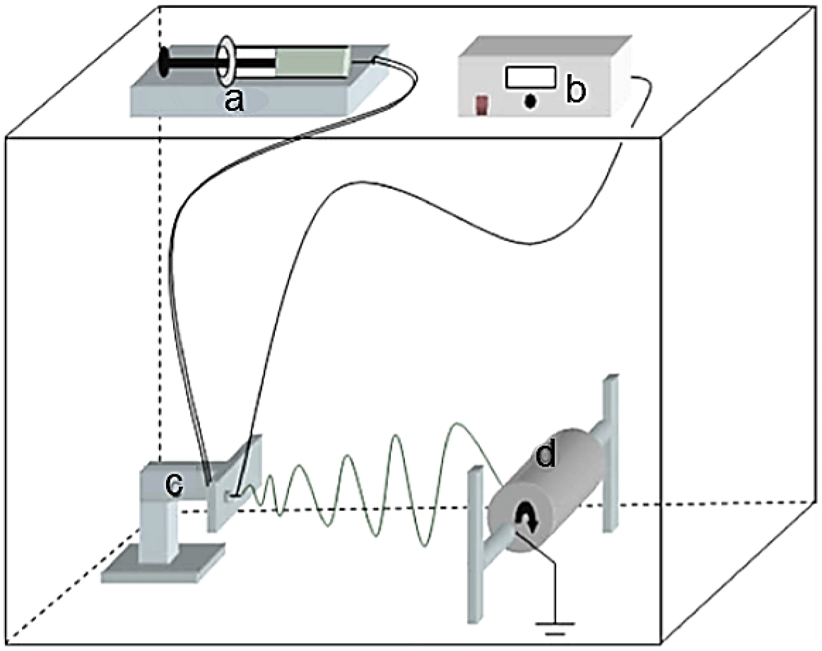
Figure 1A diagram of the custom-built electrospinning setup: (a) syringe pump, (b) high voltage supply, (c) transition stage, and (d) rotating collector.
The solution of PAN in DMF was prepared by continuously stirring the polymer in the solvent for 24 h at 60 ∘C. After obtaining the desired solution, it was left to cool and degas overnight at room temperature prior to electrospinning. The as-prepared polymeric solution was electrospun at a flow rate of 1 mL h−1 onto an aluminum foil which is peeled off before using the membrane in preparing the TFC membranes. Electrospinning was conducted at ambient temperature and humidity.
In order to compare the mechanical properties of the prepared support layer with a common support layer used for the same purpose, a polyethersulfone support sheet was prepared via the phase inversion phenomenon; 15 % PES was dissolved in DMF by applying heat and stirring for 3 h until a colorless solution formed without any polymer residue. After maintaining the solution at 60 ∘C during heating, it was left to cool at room temperature overnight for degassing. The solution was extended on a glass plate via a home-made casting knife to a thickness of 130 µm and immersed in a water bath. The solution turned to a white sheet and separated from the glass in a few seconds. The sheet was rinsed with water three times before storage and use.
2.3 Interfacial polymerization to make a TFC membrane
The TFC membranes were prepared via the interfacial polymerization reaction at the interface between MPD aqueous solution and TMC organic solution; 2 % of MPD was dissolved in DI water to prepare the aqueous solution, while the organic solution was prepared by dissolving 0.15 % of TMC in isooctane. The IP reaction was conducted on the PAN support layer as follows. First, the as-spun PAN was mounted on a glass plate and the MPD solution was poured on its top and kept in contact with the PAN support sheet for 60 s (Kadhom et al., 2016). The excess of the solution was ejected using a squeegee ruler. Then, the TMC solution was poured on the PAN sheet that contained the MPD active sites and kept in contact for 30 s. The resulting TFC membrane was then dried for 10 min at 60 ∘C and stored in DI water prior to the performance examination.
2.4 Membrane characterizations
The morphology analysis of the prepared membranes was determined using a Scanning Electron Microscope (SEM, VEGA3 – TESCAN, Czechoslovakia). The mechanical properties of the different membranes were obtained from the tensile tests in the air at 25 ∘C using an Instron microforce tester. A dynamic mechanical analysis (DMA) controlled force module was selected and a minimum of three strips (with a size of 40 mm × 5.5 mm) were tested from each type of membrane. The porosity of the membranes was estimated using the gravimetrical method. The membrane was cut as disks with a diameter of 2.54 cm (1 in.) and weighed (Wdry). Isopropyl alcohol (IPA) was used as a wetting agent and the membrane weighed after immersed in IPA (Wwet). The porosity (ε) was calculated from the following equation:
where ρIPA is the density of IPA and V is the total volume of the sample. Each membrane was tested at least three times. The membranes' wettability was studied by measuring the contact angle (Theta Lite TL-101 Thailand).
2.5 Forward osmosis performance tests
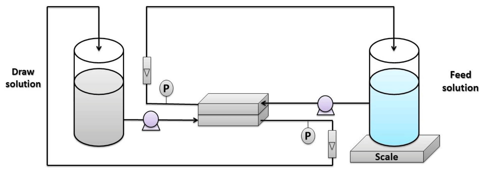
The FO tests were carried out using the experimental setup illustrated in Fig. 2. The installation consists of two tanks: one was specified for the feed solution, while the other was for the draw solution. Both solutions were pumped to the membrane cell using diaphragm pumps from Pure-water®. The membrane was installed in a custom-made cell with dimensions of 7.62 cm length, 2.54 cm width, and 0.3 cm depth. The selection of the feed and draw solutions was according to the standard methodology described by Cath et al. (2013). The DI water was used as a feed solution, while 1 M NaCl solution was used as a draw solution. The water permeation flux was estimated as follows:
where Jw is the water flux (Lm−2 h−1), Δw represents the difference in the feed solution weight (g), ρ is water density at operating temperature (g L−1), A is the actual operative area of the membrane ( m2), and t is the experiment time.
Solute flux through the membrane was estimated by monitoring the conductivity of the feed solution and using the following equation:
where Js represents the solute flux (gm−2 h−1), ΔC is the change in feed solution concentration (g L−1) (calculated from the conductivity change), and V stands for the volume of feed solution (L).
3.1 Membrane characterization
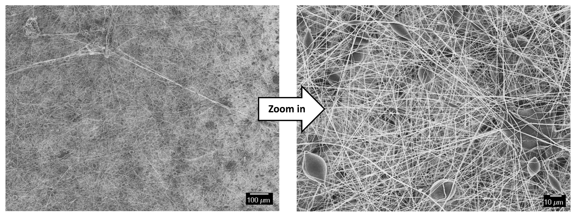
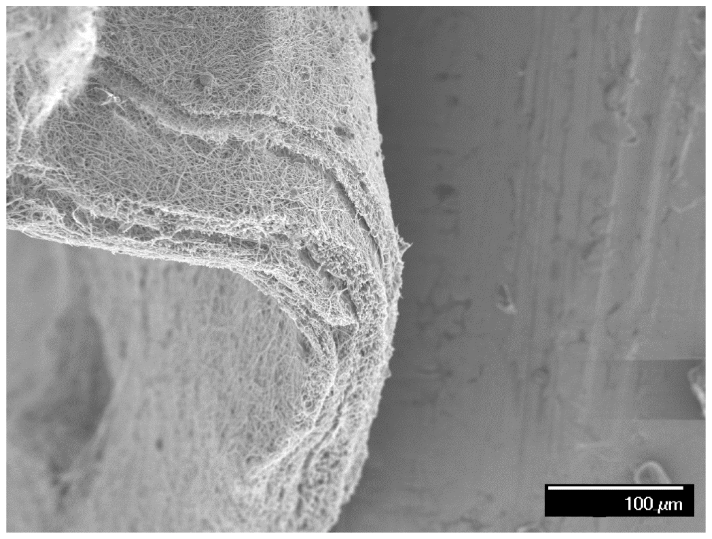
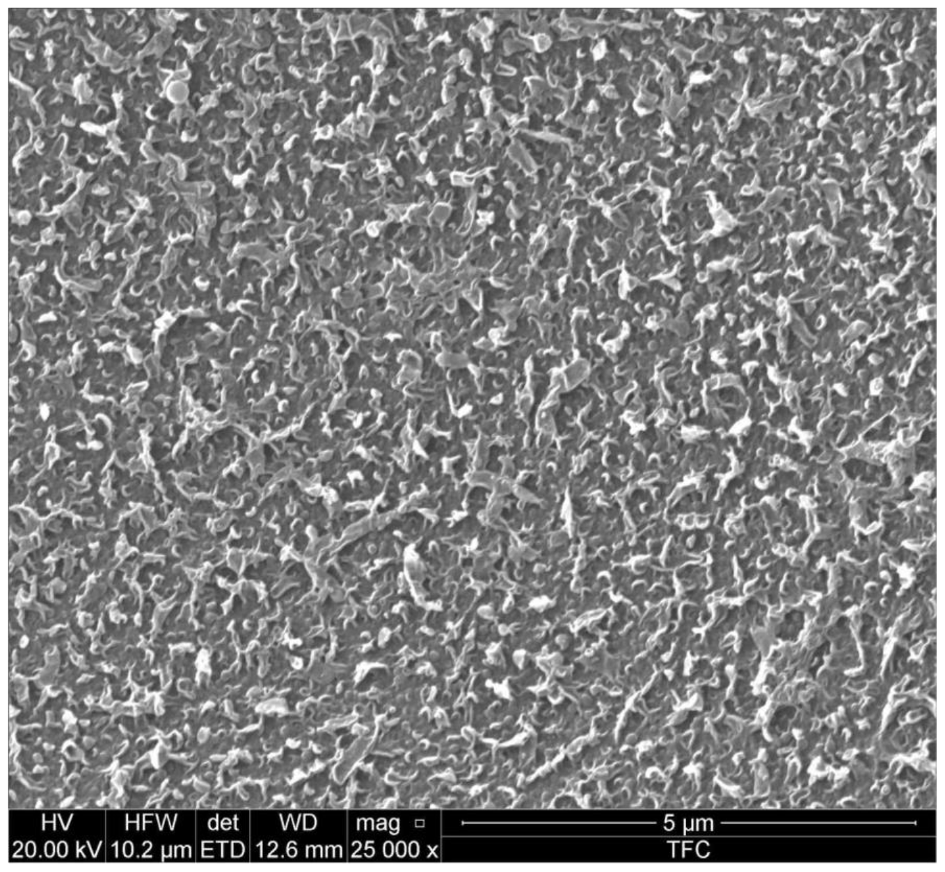
Figure 3 illustrates the SEM images of the PAN's support layer that was prepared by the electrospinning technique. It can be observed that the membrane is structured by smooth and uniform fibers with an approximate diameter of 250 nm. The cross-sectional SEM image (Fig. 4) shows that the membrane consists of nanofibrous layers with a thickness of about 75 µm. It can also be noticed that the underlying nanofibers have a very high porosity on their surfaces. This could ensure maximum contact between PAN nanofibers with the draw solution during the forward osmosis operation, which means a higher mass transfer area and consequently higher water flux. Figure 5 illustrates the surface morphology of the PAN nanofiber membrane after the interfacial polymerization reaction. Also, it can be seen that the polyamide selective membrane was successfully formed on the PAN nanofiber support sheet. It can be seen from the SEM image after the IP reaction that it has a leaf-like morphology compared to the PAN support layer, which has a nanofibrous structure. It was reported in the literature that the leaf-like structure confirms the formation of the polyamide selective layer. The contact angle measurement of the prepared membranes showed that it has a hydrophilic surface with an average contact angle of 35∘. The hydrophilicity of the membrane's surface is an important factor in the osmotically driven membrane processes (Darwish et al., 2020). This could be explained as the solutes can exclusively diffuse within the wetted area of the support sheet. Ultimately, the unsaturated parts inside the internal structure of the support layer could not be calculated as an actual mass transfer area. As much as the internal surfaces of the pores and inner vacancy get wet, the porous support layer can contribute to producing a membrane with a better osmotic water flux performance.

3.2 Support sheet mechanical properties and porosity
3.2.1 Mechanical properties
Using a support layer for the TFC membrane that is usually applied in nanofiltration, reverse osmosis, and forward osmosis is inevitable due to the tiny thickness of the active membrane. The support layer was found to significantly affect the total performance and is commonly made of polymers. Many factors could influence layer usage, such as its raw material, method and conditions of preparation, doping additives, porosity, and tortuosity (Kadhom and Deng, 2019). In most cases, the support layer is manufactured using the phase inversion phenomenon for a low hydrophilicity polymer. In this work, a PAN layer was synthesized using the electrospinning, which is expected to produce higher internal porosity than the sheets produced via phase inversion. Therefore, the mechanical properties were studied and compared to the commonly used support layer produced by phase inversion.
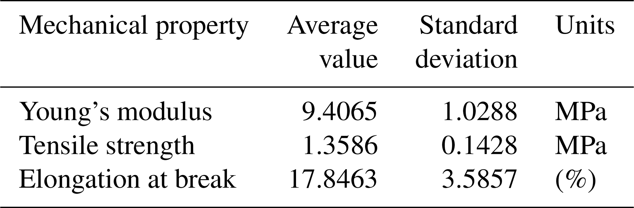
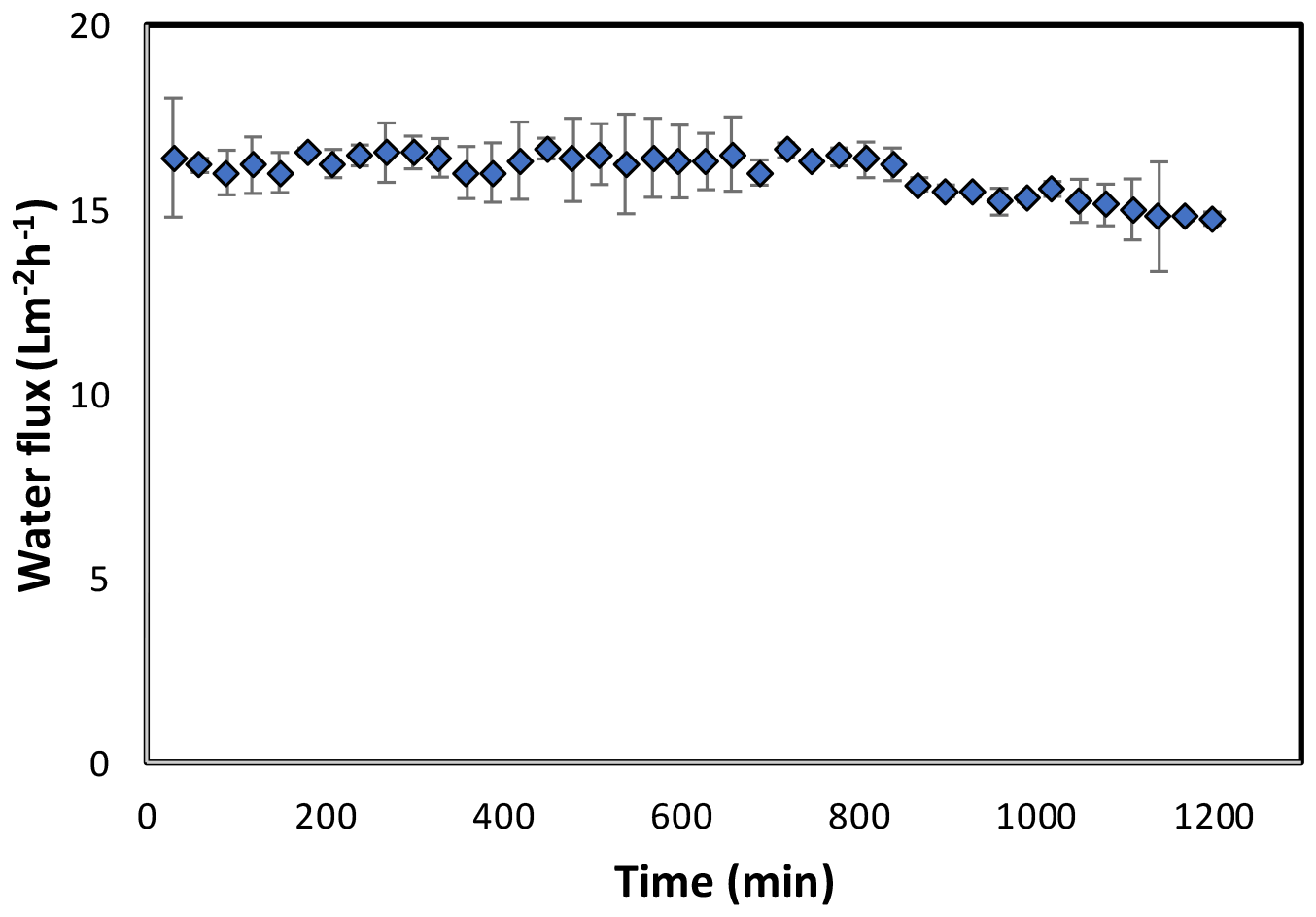
Figure 7Forward osmosis water flux for the PAN-TFC membrane. Experimental conditions: feed solution: DI water, draw solution: 1 M NaCl, FO mode, volumetric flow rate of feed and draw 0.6 L min−1, temp 25 ∘C, zero transmembrane pressure. Results are an average of three experiments with different coupons. Error bars indicate standard deviation.
Figure 6 shows the relation between the stress and strain of the PAN sheet. It can be observed that the maximum stress was 1.258 MPa, which was associated with the strain of 15.31 %. When these values were compared with a 15 % polyethersulfone support sheet (as an example of the commonly applied support layers), the stress is lower but the strain is higher. The measured stress and strain of the PES sheet were around 2.45 MPa and 8.7 %, respectively. It can be noted that the PAN sheets had a lower mechanical strength but a higher elongation rate. This result is expected due to the method of preparation, wherein the electrospinning nanofibers are made individually and connect with each other on the rotating cylinder. While in the phase inversion, the sheet formed by stiffening the polymer and discarding the solvent. The average values of other mechanical properties were listed in Table 1 with the standard deviation of three measurement values.
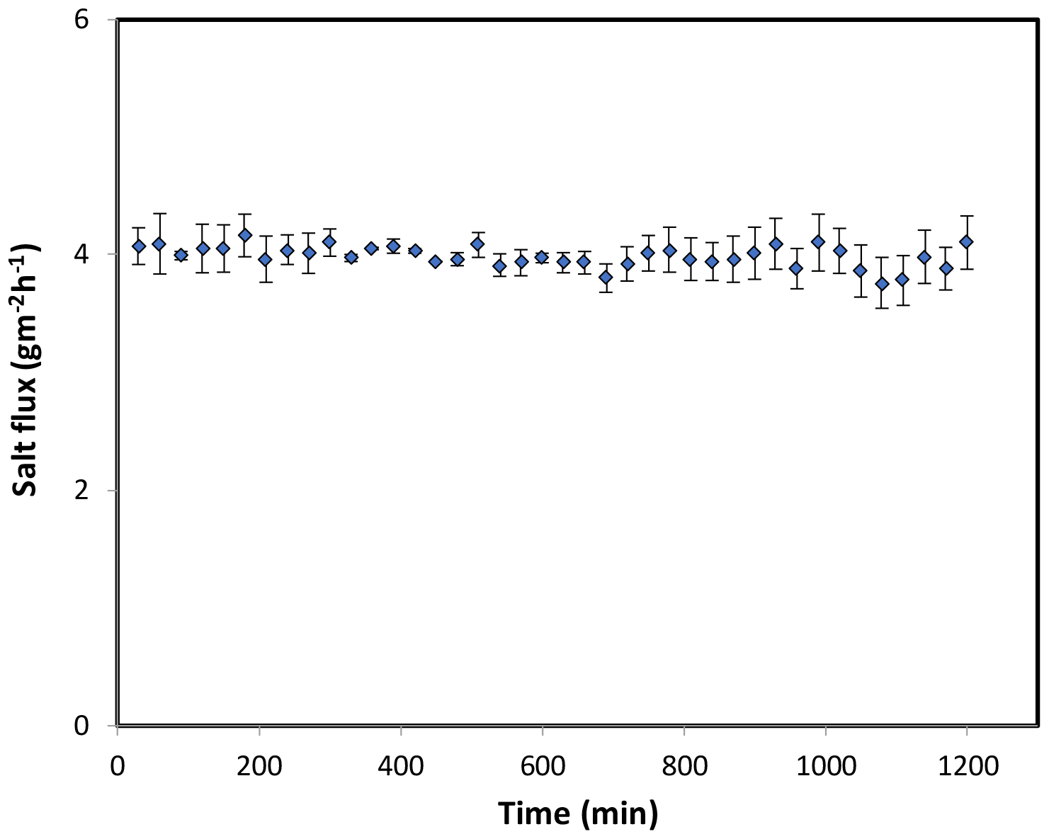
Figure 8Forward osmosis salt flux for the PAN-TFC membrane. Experimental conditions: feed solution: DI water, draw solution: 1 M NaCl, FO mode, volumetric flow rate of feed and draw 0.6 L min−1, temp 25 ∘C, zero transmembrane pressure. Results are an average of three experiments with different trails. Error bars indicate standard deviation.
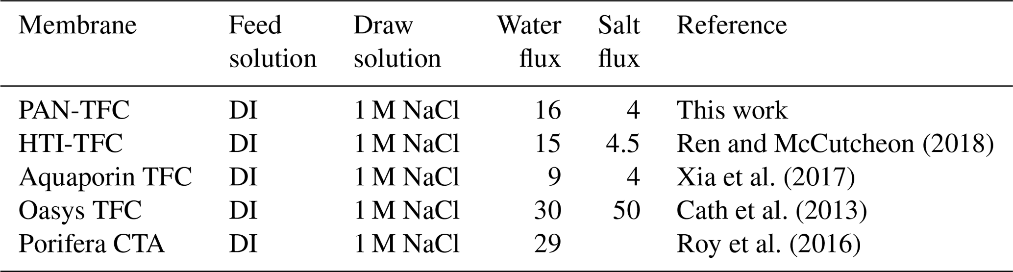
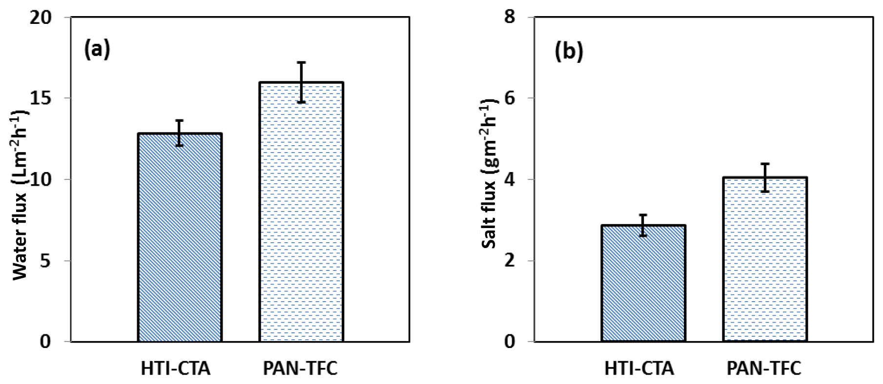
Figure 9Forward osmosis (a) water flux and (b) salt flux for the PAN-TFC membrane. Experimental conditions: feed solution: DI water, draw solution: 1 M NaCl, FO mode, volumetric flow rate of feed and draw 0.6 L min−1, temp 25 ∘C, zero transmembrane pressure. Results are an average of three experiments with different coupons. Error bars indicate standard deviation.
3.2.2 Porosity
A PAN support layer was prepared by the electrospinning to achieve a high porosity. However, the average porosity values of the PAN and classic PES layers were 92.07 % ± 2.09 and 60.0 % ± 1.53, respectively. From these values, it can be seen that the PAN sheet is more porous than the PES sheet. This could help in penetrating the water and, anyway, solute through the membrane structure, which could improve the water flux. Higher porosity means lower unreached spaces and dead ends.
3.3 Membrane performance in FO operation
The osmotic efficiency of the TFC membrane supported by the nanofiber layer was examined using DI water as a feed solution, whereas 1 M NaCl solution was used as a draw solution according to the standard methodology for testing the osmotically driven membranes (Cath et al., 2013). Results of water flux and salt reverse flux are clarified in Figs. 7 and 8, respectively. PAN-TFC membrane showed a stable flux of about 16 LMH for 20 h of operation. Reverse salt flux exhibited similar behavior with an average value of about 4 GMH. In order to compare the performance of the PAN-TFC membrane with commercial membranes, we tested CTA membranes from HTI under the same operating conditions; the results were illustrated in Fig. 9. Also, a comparison of the PAN-TFC membrane with some of the commercially available FO membranes can be found in Table 2. It can be distinguished from the figure that the PAN-TFC membrane's water flux was higher than the HTI-CTA membrane's water flux. This could be attributed to the highly porous surface structure of the nanofiber support layer for the PAN-TFC membrane; this porous surface generates a more effective mass transfer area and consequently higher water flux. However, the reverse salt flux of the commercial membrane was lower compared to the PAN-TFC membrane. This could be ascribed to its better mechanical strength and rigidity compared with the nanofibrous composite membranes, which commonly have modest mechanical properties. Nevertheless, the FO applications are famous for having low or no hydraulic pressure required to drive the process; here, it can result in the osmotic efficiency of the membrane being more important than its rigidity.
TFC membrane with a fibrous structure was prepared in this research and tested for forward osmosis application. The electrospinning setup was made from locally available parts. This system exhibited stable operation in making the electrospun nanofiber membrane. The prepared TFC membrane showed good performance in terms of water flux and salt rejection. TFC-PAN membranes showed a stable water flux with an average value of 16 LMH compared to the CTA commercial membranes with 13 LMH water flux. Future research can focus on incorporating specific nanoparticles to enhance membrane performance. Also, studying the exposure time of MPD and TMC on the performance of the membrane is highly recommended.
No data sets were used in this article.
MA initiated the project and wrote the first draft of the paper. MK reviewed the original paper, made editorial corrections and prepared the figures and tables. KK conducted the experiments and recorded the original data. BW and NA made the characterizations of the membranes and analyzed the obtained data.
The authors declare that they have no conflict of interest.
The authors would like to thank their affiliations, the Ministry of Science and Technology, Alkarkh University of Science, University of Baghdad, and the University of Wasit, for partially supporting this work.
This paper was edited by Luuk Rietveld and reviewed by Bas Heijman and one anonymous referee.
Al-Furaiji, M., Benes, N., Nijmeijer, A., and McCutcheon, J. R.: Use of a Forward Osmosis–Membrane Distillation Integrated Process in the Treatment of High-Salinity Oily Wastewater, Ind. Eng. Chem. Res., 58, 956–962, https://doi.org/10.1021/acs.iecr.8b04875, 2019.
Al-Furaiji, M. H. O., Arena, J. T., Chowdhury, M., Benes, N., Nijmeijer, A., and McCutcheon, J. R.: Use of forward osmosis in treatment of hyper-saline water, Desalin. Water Treat., 133, 1–9, https://doi.org/10.5004/dwt.2018.22851, 2018.
Ang, W. L., Wahab Mohammad, A., Johnson, D., and Hilal, N.: Forward osmosis research trends in desalination and wastewater treatment: A review of research trends over the past decade, J. Water Process Eng., 31, 100886, https://doi.org/10.1016/j.jwpe.2019.100886, 2019.
Bui, N. N. and McCutcheon, J. R.: Hydrophilic nanofibers as new supports for thin film composite membranes for engineered osmosis, Environ. Sci. Technol., 47, 1761–1769, https://doi.org/10.1021/es304215g, 2013.
Cath, T. Y., Adams, D., and Childress, A. E.: Membrane contactor processes for wastewater reclamation in space: II. Combined direct osmosis, osmotic distillation, and membrane distillation for treatment of metabolic wastewater, J. Memb. Sci., 257, 111–119, https://doi.org/10.1016/j.memsci.2004.07.039, 2005.
Cath, T. Y., Childress, A. E., and Elimelech, M.: Forward osmosis: Principles, applications, and recent developments, J. Memb. Sci., 281, 70–87, https://doi.org/10.1016/j.memsci.2006.05.048, 2006.
Cath, T. Y., Elimelech, M., McCutcheon, J. R., McGinnis, R. L., Achilli, A., Anastasio, D., Brady, A. R., Childress, A. E., Farr, I. V., Hancock, N. T., Lampi, J., Nghiem, L. D., Xie, M., and Yip, N. Y.: Standard Methodology for Evaluating Membrane Performance in Osmotically Driven Membrane Processes, Desalination, 312, 31–38, https://doi.org/10.1016/j.desal.2012.07.005, 2013.
Chowdhury, M. R., Huang, L., and McCutcheon, J. R.: Thin Film Composite Membranes for Forward Osmosis Supported by Commercial Nanofiber Nonwovens, Ind. Eng. Chem. Res., 56, 1057–1063, https://doi.org/10.1021/acs.iecr.6b04256, 2017.
Darwish, N. B., Alkhudhiri, A., AlRomaih, H., Alalawi, A., Leaper, M. C. and Hilal, N.: Effect of lithium chloride additive on forward osmosis membranes performance, J. Water Process Eng., 33, 101049, https://doi.org/10.1016/j.jwpe.2019.101049, 2020.
Huang, L. and McCutcheon, J. R.: Hydrophilic nylon 6,6 nanofibers supported thin film composite membranes for engineered osmosis, J. Memb. Sci., 457, 162–169, https://doi.org/10.1016/j.memsci.2014.01.040, 2014.
Kadhom, M. and Deng, B.: Synthesis of high-performance thin film composite (TFC) membranes by controlling the preparation conditions: Technical notes, J. Water Process Eng., 30, 100542, https://doi.org/10.1016/j.jwpe.2017.12.011, 2019.
Kadhom, M., Yin, J., and Deng, B.: A thin film nanocomposite membrane with MCM-41 silica nanoparticles for brackish water purification, Membranes (Basel), 6, 50, https://doi.org/10.3390/membranes6040050, 2016.
Linares, R. V., Li, Z., Elimelech, M., Amy, G., and Vrouwenvelder, H. (Eds.): Recent Developments in Forward Osmosis Processes, IWA Publishing, https://doi.org/10.2166/9781780408125, 2017.
McCutcheon, J. R., McGinnis, R. L., and Elimelech, M.: A novel ammonia-carbon dioxide forward (direct) osmosis desalination process, Desalination, 174, 1–11, https://doi.org/10.1016/j.desal.2004.11.002, 2005.
Ren, J. and McCutcheon, J. R.: A new commercial thin film composite membrane for forward osmosis, Desalination, 343, 187–193, https://doi.org/10.1016/j.desal.2013.11.026, 2014.
Ren, J. and McCutcheon, J. R.: A new commercial biomimetic hollow fiber membrane for forward osmosis, Desalination, 442, 44–50, https://doi.org/10.1016/j.desal.2018.04.015, 2018.
Roy, D., Rahni, M., Pierre, P., and Yargeau, V.: Forward osmosis for the concentration and reuse of process saline wastewater, Chem. Eng. J., 287, 277–284, https://doi.org/10.1016/j.cej.2015.11.012, 2016.
Waisi, B. I., Manickam, S. S., Benes, N. E., Nijmeijer, A., and McCutcheon, J. R.: Activated Carbon Nanofiber Nonwovens: Improving Strength and Surface Area by Tuning Fabrication Procedure, Ind. Eng. Chem. Res., 58, 4084–4089, https://doi.org/10.1021/acs.iecr.8b05612, 2019.
Xia, L., Andersen, M. F., Hélix-Nielsen, C., and McCutcheon, J. R.: Novel Commercial Aquaporin Flat-Sheet Membrane for Forward Osmosis, Ind. Eng. Chem. Res., 56, 11919–11925, https://doi.org/10.1021/acs.iecr.7b02368, 2017.